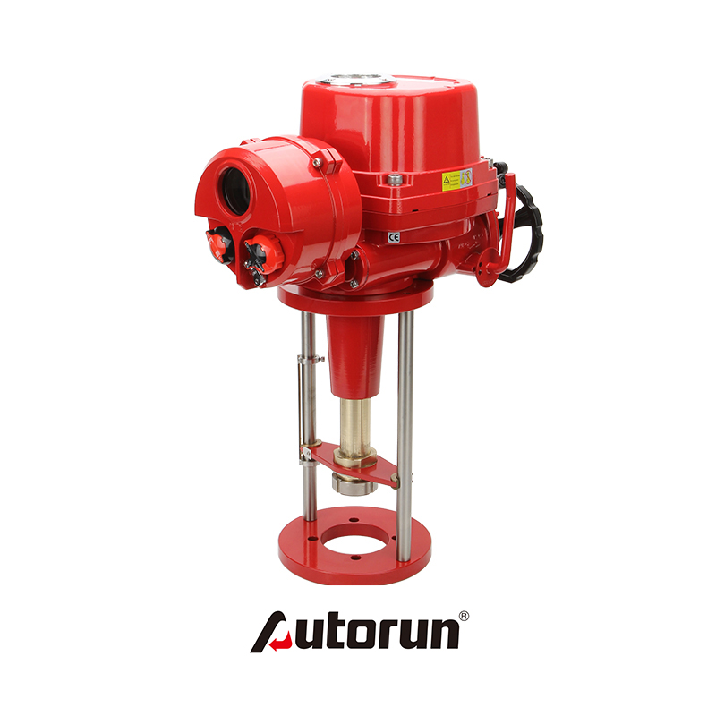
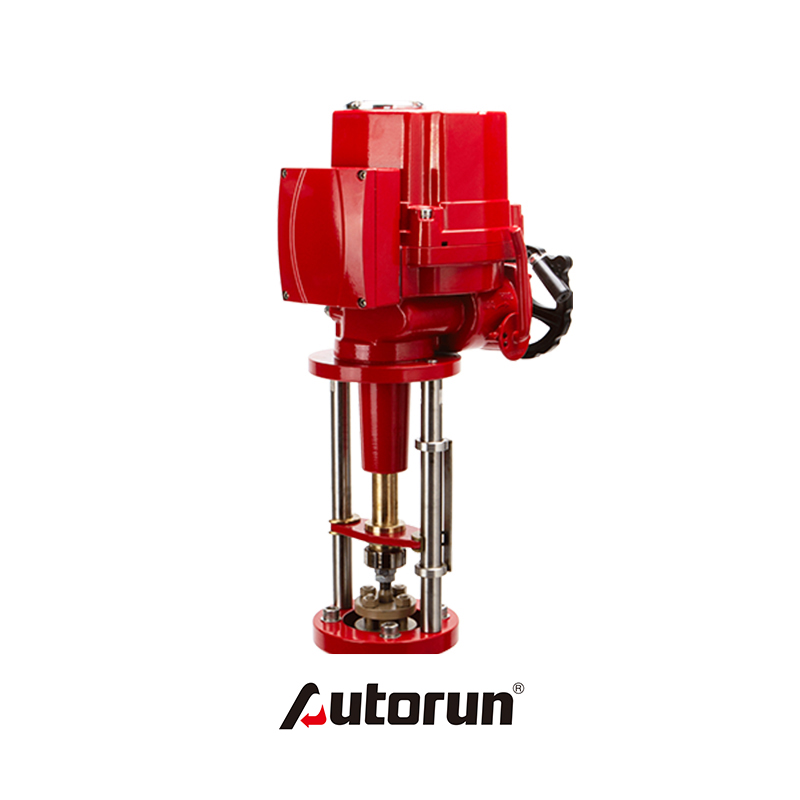
Electrical valve positioner is one of the most important accessories of pneumatic control valve. It realizes the function of receiving control signals to accurately locate the valve travel position. When pneumatic control valve leaves the factory, positioner and control valve have been calibrated. But when the valve is installed on the pipeline, it often needs to be calibrated again. The conventional calibration method is: calibrating 5 points, namely 4mA. 8mA, 12mA, 16mA, 20mA, at 12mA, the feedback rod of positioner is in horizontal position. Valve position should be at 0, 25%, 75% and 100% of the other signals respectively, and the rotation angle of the feedback rod is less than plus or minus 45 degrees. The deviation between zero and fullness can be corrected by adjusting the corresponding screw separately. Normally, if the valve stroke and given letter are given, the deviation between zero and fullness can be adjusted separately. Number-to-number correspondence means that the calibration is completed.
One of the main problems in valve closure is how to achieve the full load of the seat to close the valve tightly. The usual method is to calibrate the valve so that the closing parts (such as plugs, diaphragms, discs, etc.) are positioned exactly on the seat, rather than confirming whether the closing parts are completely on the seat. In order to maintain the design leakage and avoid the corrosion of the sealing surface, it is necessary to design the appropriate sealing load.
Single-acting pneumatic actuators are usually designed with thin film structure. With this design method, the use of spring can reduce the seat load, but also can withstand all closing pressure. Typical double-acting pneumatic actuator adopts piston design. With this design method, unlike the membrane design, the supply pressure does not need to be limited. In order to achieve a higher closed pressure, the full load supply pressure can be applied. For piston design, the higher the pressure, the better the stability and control sensitivity of the valve.
Many designers usually use 4-20mA signal as information signal instead of power signal. For thin film actuators, the power signal not only determines the location of the closing parts, but also drives the gas source to be connected and the valve to be closed. When the valve is calibrated and the valve is closed, the signal value is exactly 4 mA. In order to ensure that no seat load is generated, auxiliary power supply is used in valve design. Seat load occurs only when the control signal drops below 4mA, but this signal is not usually present in the control system. Therefore, the purpose of this discussion is only to calibrate the valve so that it can be closed accurately and tightly; when closed, the seat is in full load state. When the signal value is 3-5% of the operating value, the abnormal calibration is carried out to make the valve in place on the seat. Or when the stroke of the valve reaches the preset position, the fast acting relay changes the positioner signal so that the valve is completely closed and the full load closing pressure is applied.