Pneumatic actuatorHow does it work?
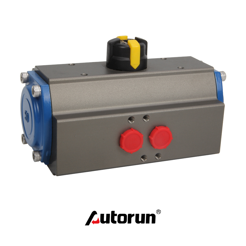
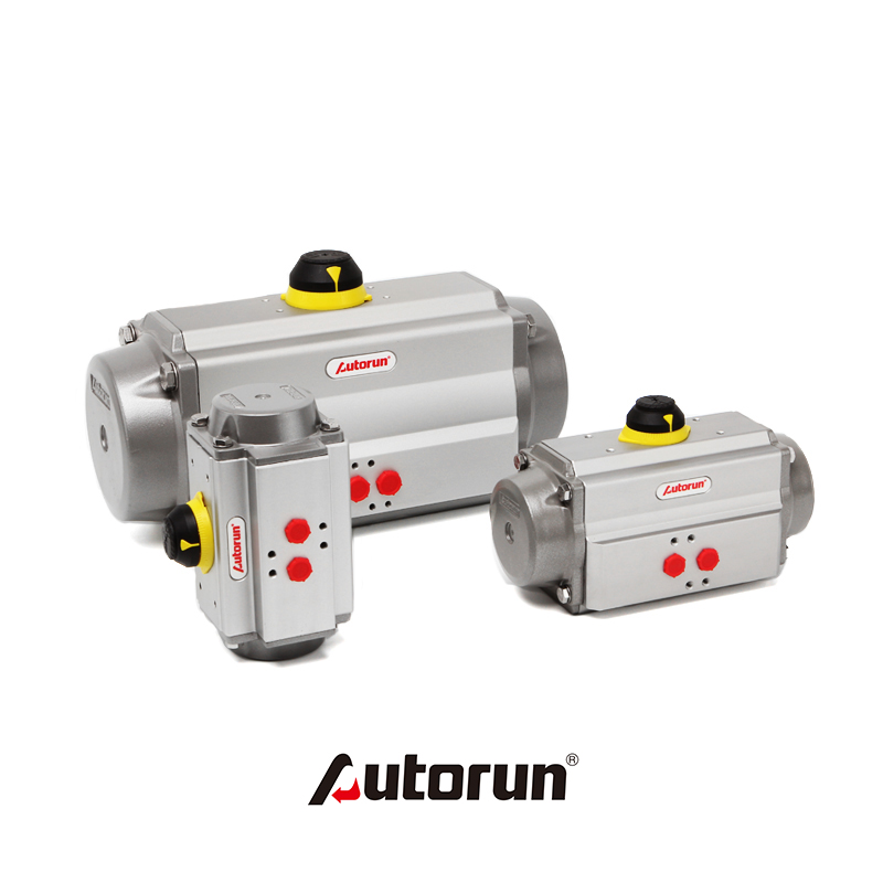
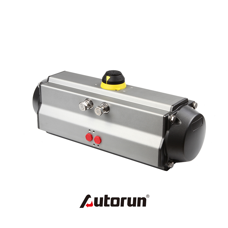
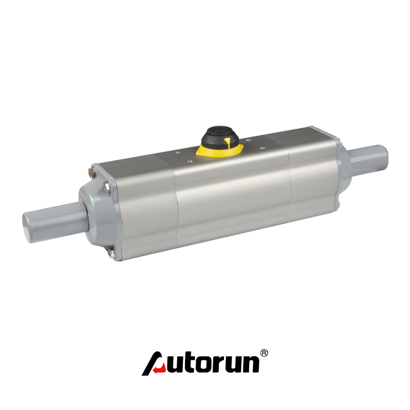
When compressed air enters the pneumatic actuator from nozzle A, the gas pushes the piston to move in a straight line toward both ends (cylinder head end). The rack on the piston drives the gear on the rotating shaft to rotate 90 degrees counterclockwise, and the valve is opened. At this time, the gas at both ends of the pneumatic actuator valve is discharged with the B-tube nozzle. Conversely, when compressed air enters the two ends of the pneumatic actuator from the B-shaped nozzle, the gas pushes the two plugs to move in a straight line towards the middle. The rack on the piston drives the gear on the rotating shaft to rotate 90 degrees clockwise, and the valve is closed. At this time, the gas in the middle of the pneumatic actuator is discharged with the A-tube nozzle. The above is the standard transmission principle.

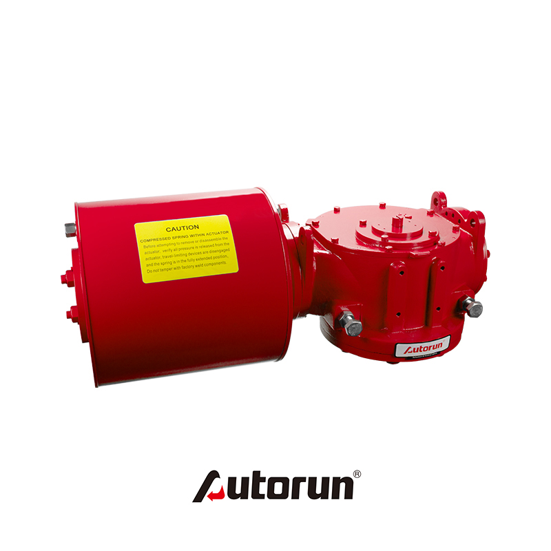
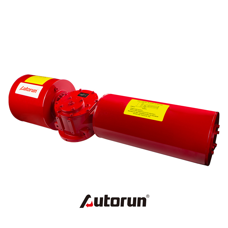
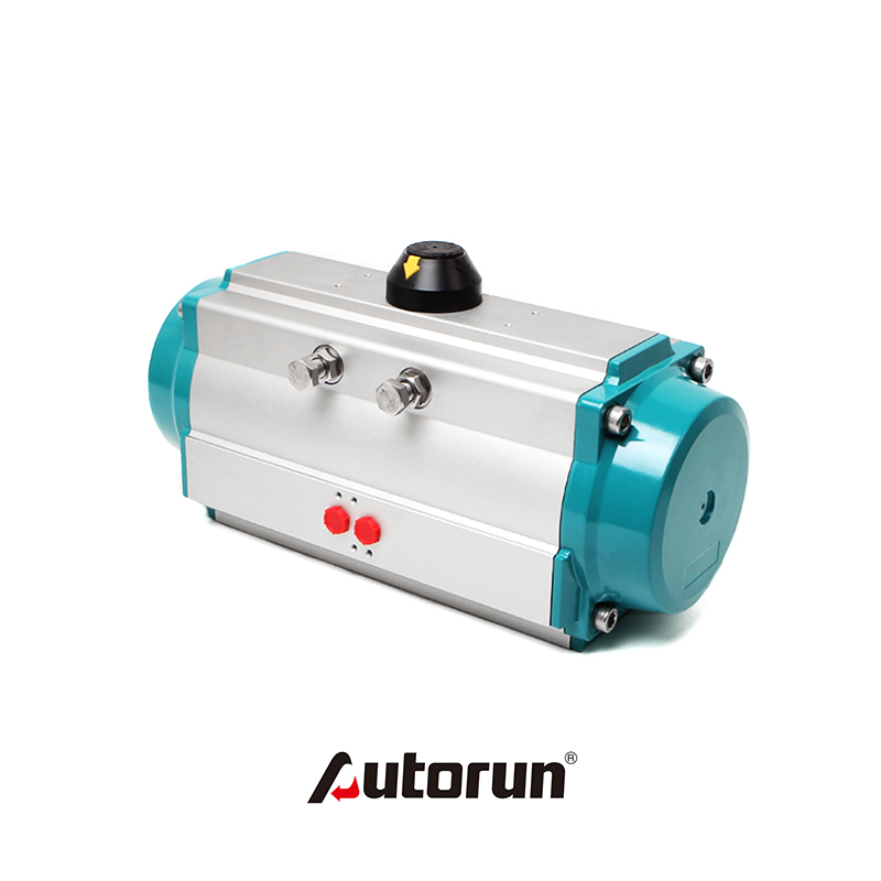
According to user's demand, pneumatic actuator can be equipped with the transmission principle opposite to the standard type, that is, to select the standard axis to turn clockwise to open the valve and counter-clockwise to turn to close the valve. Single acting (spring reset type) pneumatic actuator A pipe nozzle is the intake port, B pipe nozzle is the exhaust port (B pipe nozzle should be installed muffler). The intake of A-tube nozzle is to open the valve, and the valve is closed by spring force when the air is cut off.
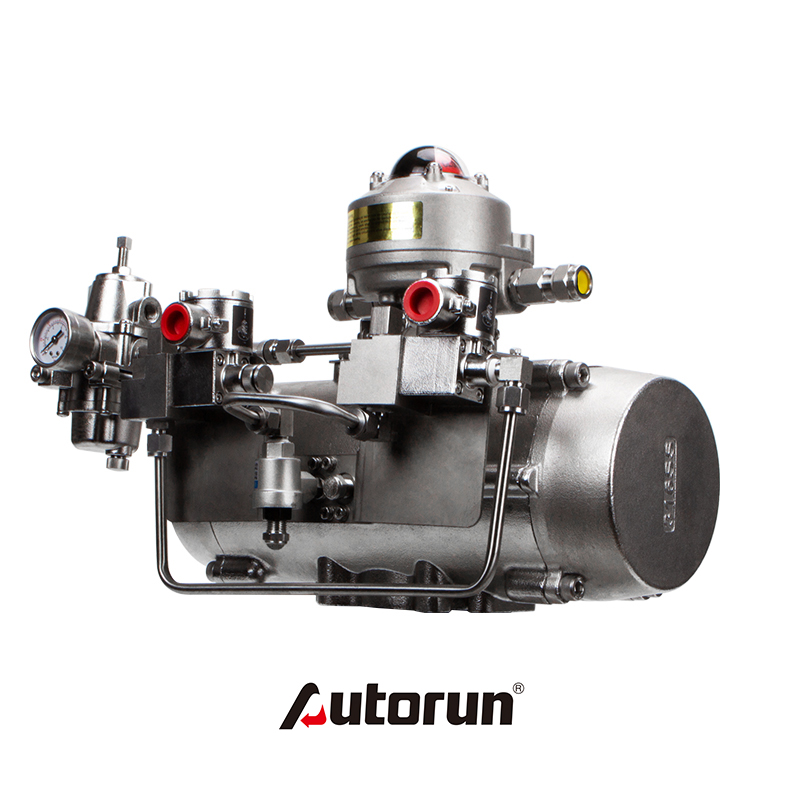
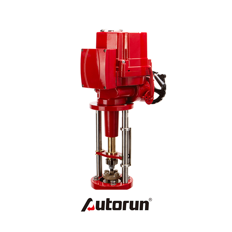
The types and structures of the regulators of pneumatic actuators are basically the same, mainly because the actuators are different. Therefore, the introduction of pneumatic actuator is divided into two parts: actuator and control valve.
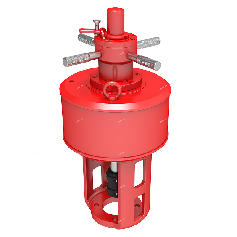
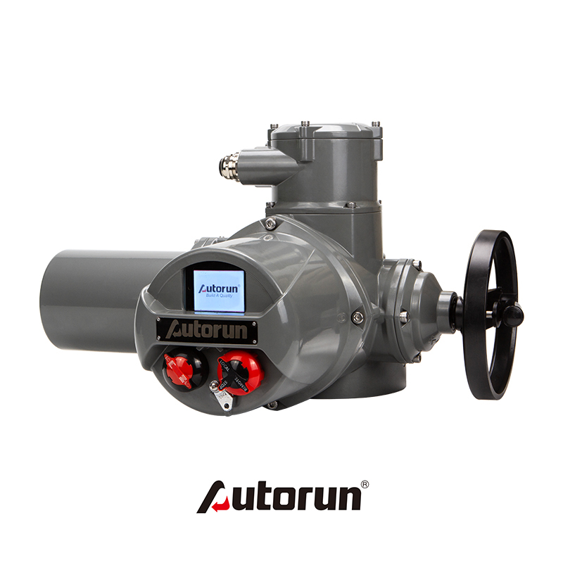
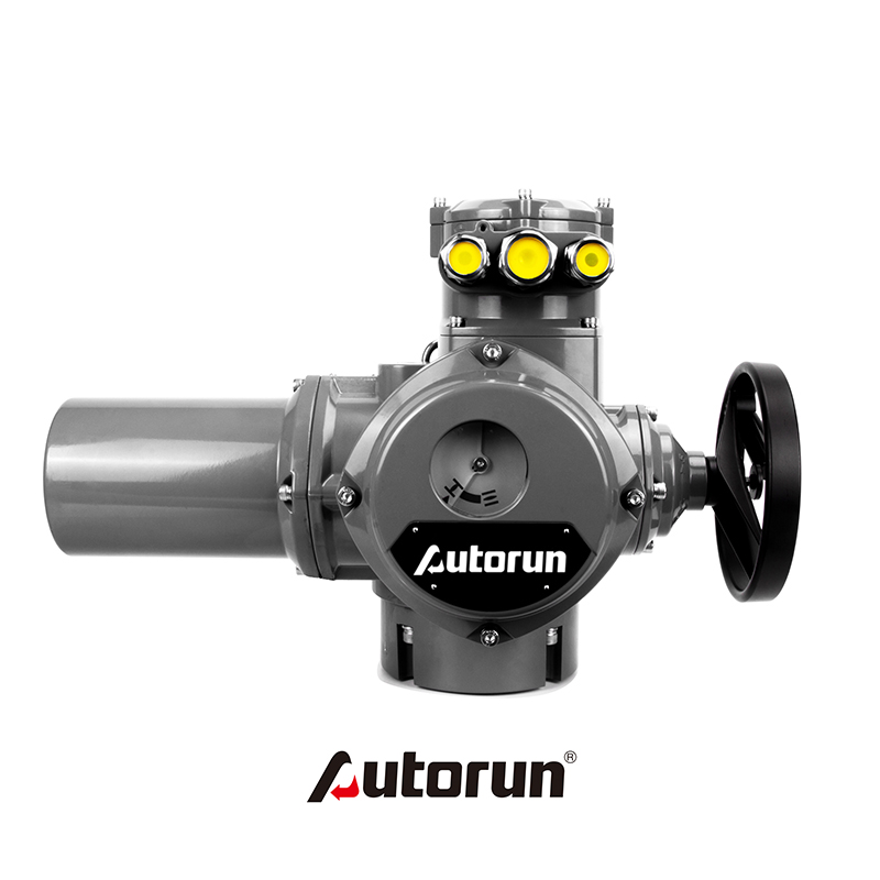
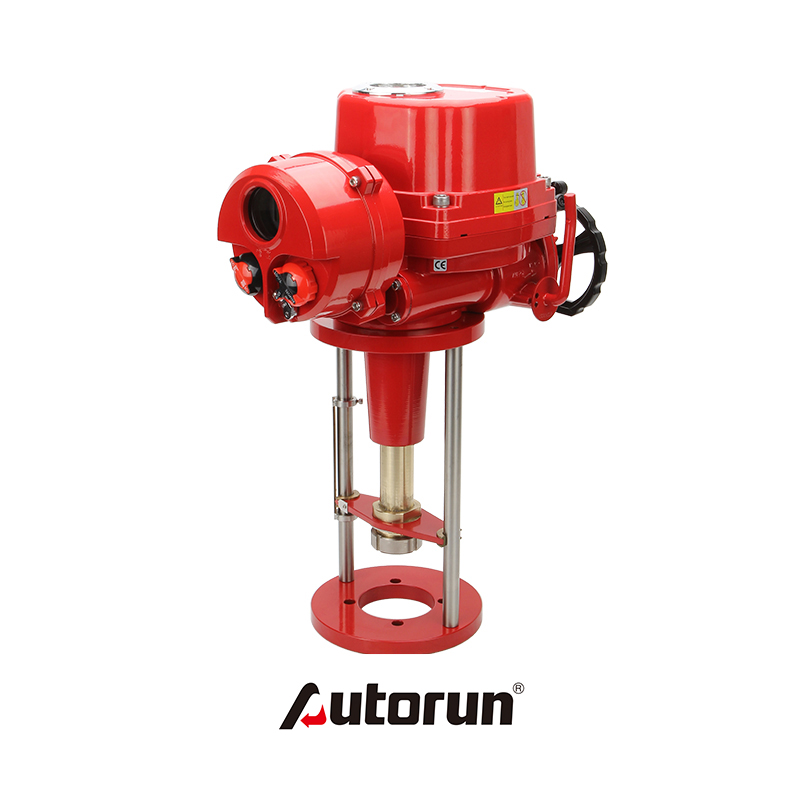
Pneumatic actuator is composed of actuator and regulating valve (regulating mechanism). According to the size of the control signal, the corresponding thrust is generated to push the control valve. The regulating valve is the regulating part of the pneumatic actuator. Under the thrust of the actuator, the regulating valve produces a certain displacement or rotation angle to directly regulate the flow of fluid.
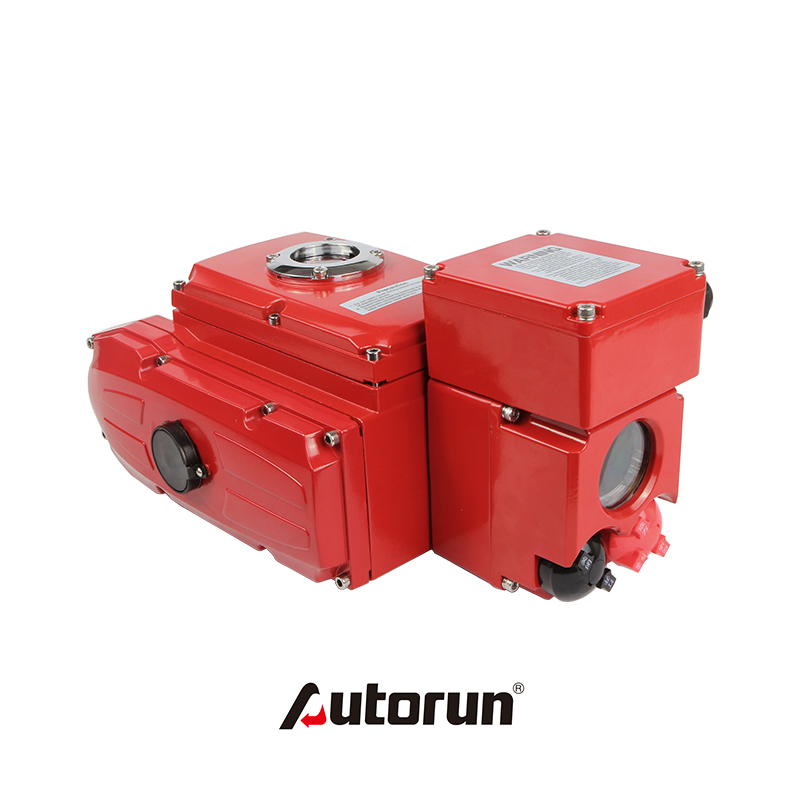
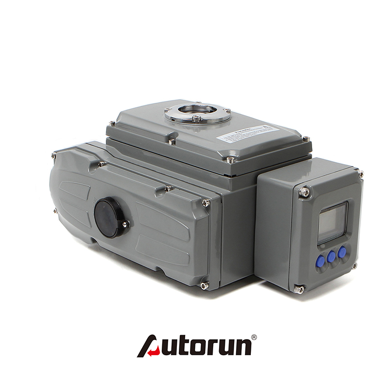
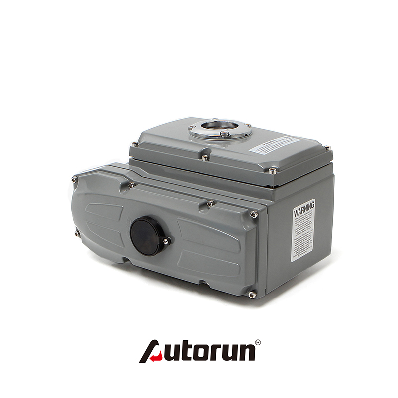
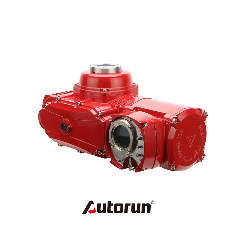
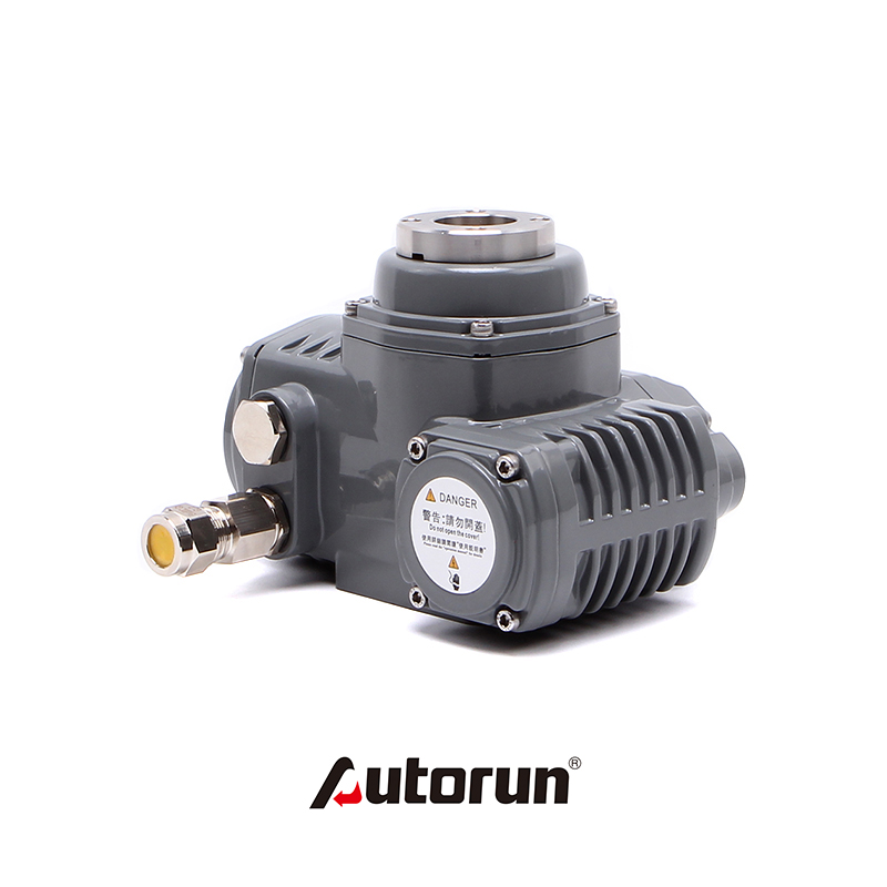
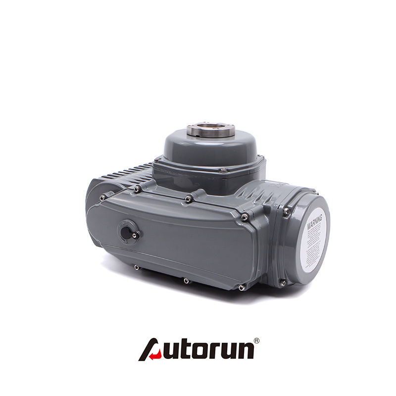
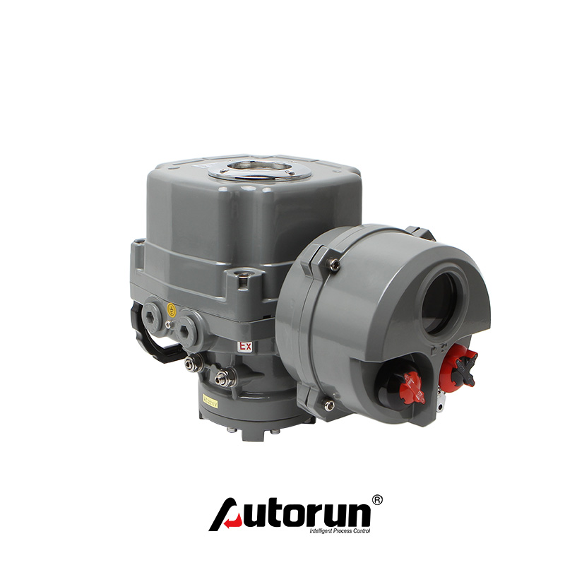
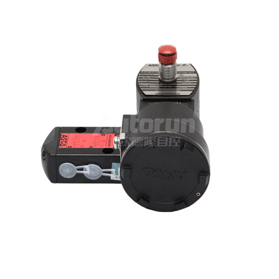
1��、Pneumatic devices are mainly composed of cylinders, pistons, gear shafts, end caps, seals, screws, etc. A complete set of pneumatic devices should also include opening indication, travel limit, solenoid valve, positioner, pneumatic components, manual mechanism, signal feedback and other components.
2、Connection dimensions between pneumatic devices and valves shall comply with the requirements of ISO5211 (Part), GB/T12222 and GB/T12223.
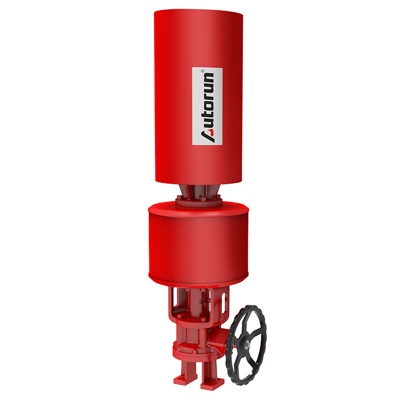
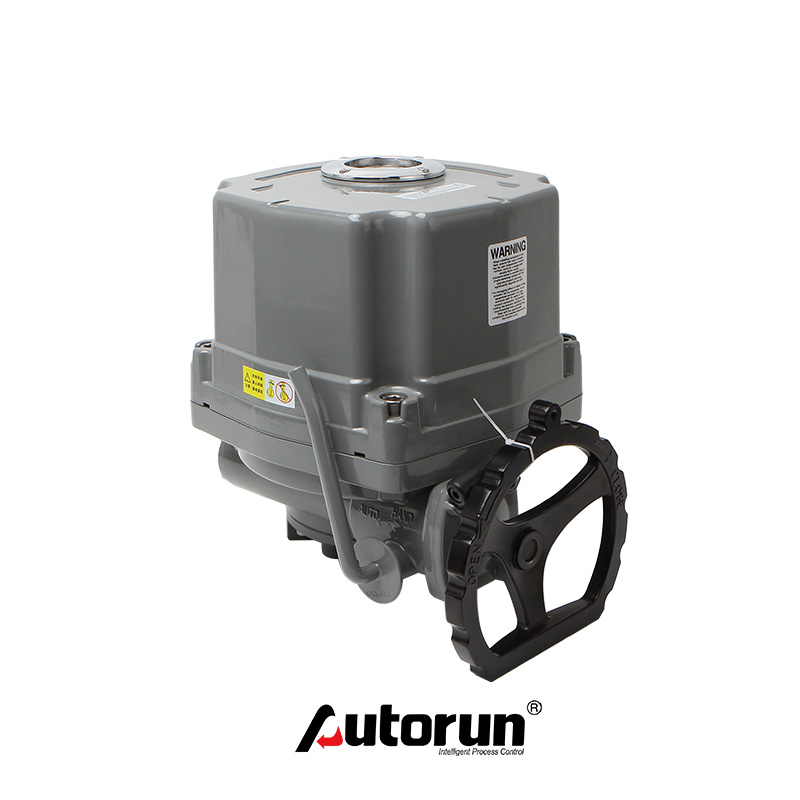
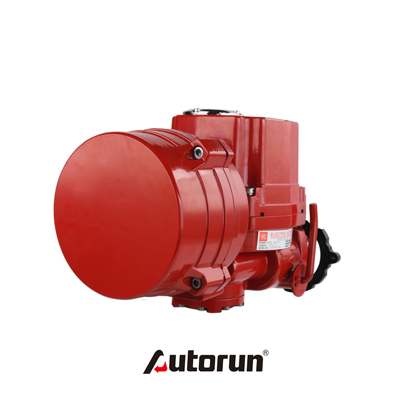
3�、When the air source is interrupted, the pneumatic device with the manual mechanism should be able to open and close the pneumatic ball valve. When facing the handwheel, the handwheel or handle should rotate counterclockwise to open the valve and clockwise to close the valve.
4、When the end of piston rod is internal and external threads, there should be a suitable wrench opening for standard wrench.
5����、The piston sealing ring should be easy to replace and repair.
6����、For a pneumatic device with a buffer mechanism, the stroke length of the buffer mechanism can be specified by reference.
7、The pneumatic device with adjustable buffer mechanism shall have a mechanism for adjusting its buffer function outside the cylinder block.
8�、Thread dimensions of cylinder inlet and outlet shall comply with MANUR NORM (Annex Standard) sypv, GB/T7306.1, GB/T7306.2 and GB/T7307.